What is ASME U-Stamp certification?
The ASME U-Stamp is a globally recognized certification issued by the American Society of Mechanical Engineers (ASME). It signifies that a pressure vessel meets the rigorous safety, design, and quality standards outlined in ASME Section VIII. This certification is essential in many geographies for manufacturers supplying pressure vessels for industries such as oil & gas, petrochemicals, and energy, where operational safety under extreme conditions is of paramount importance.
Roadmap to ASME U-Stamp Certification
GPE recently underwent a re-certification audit for the ASME U-Stamp. This audit, conducted by ASME with support from an authorized inspection agency (AIA) Hartford Steam Boiler (HSB), reaffirmed our dedication to engineering excellence as we successfully renewed our certification.
The certification process required meticulous planning, precise documentation, and adherence to ASME codes.
Below are the key documents and steps involved:
1. ASME Quality Control Manual: This cornerstone document outlines the manufacturer’s adherence to ASME
guidelines, detailing every step from material traceability to final inspection protocols.
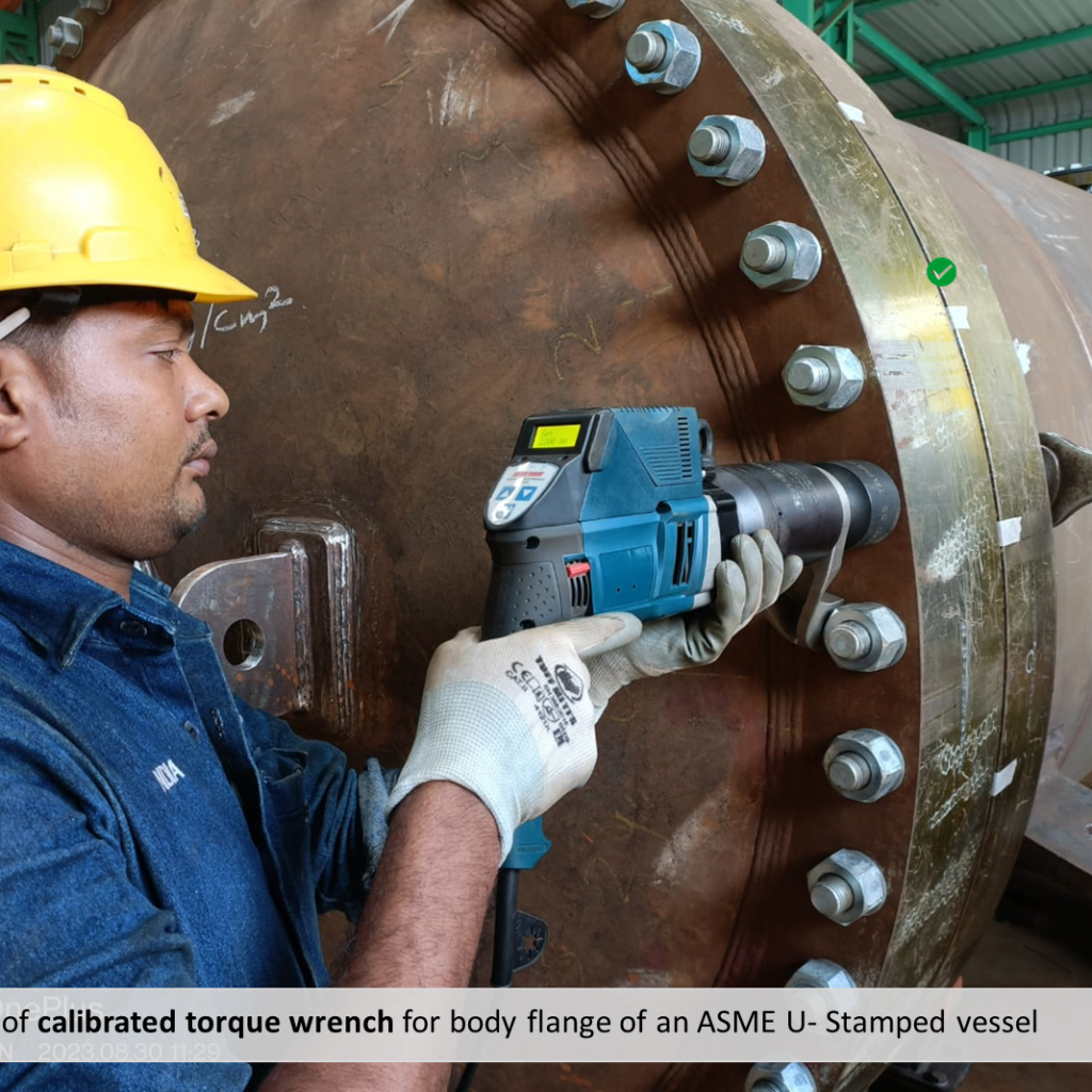
2. Certified Welding Procedures: WPS, PQR, and WPQ ensure consistent weld quality, essential for pressure
vessel integrity.
3. Material Test Certificates (MTCs): These establish traceability and verify that materials meet ASME
specifications.
4. Inspection and Testing Records: A comprehensive record of all non-destructive and performance tests
validates the vessel’s safety.
The ASME certification process also includes a joint review with an Authorized Inspector (AI), emphasizing the
importance of meticulous preparation.
By adhering to these requirements and clearing all the audit observations, GPE got it U-Stamp certificate renewed from July 2024 to July 2027.
GPE has supplied U-Stamp-certified process equipment to customers worldwide, catering to diverse industries and applications, such as:
- Adsorber vessels
- Clay treater vessels
- Feed drum
- Heater vessel
- Separator
- After filter
- Suction and Discharge volume bottles
- Desulfurization vessels,
- VOC removal vessels,
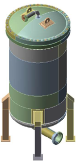
- Blowdown vessels
- Stillage coolers,
- Tailgas coolers,
- LFG precoolers,
- Recirculate Coolers, etc.
Key ASME Standards – Designing a U-Stamp Pressure Vessel in Cyclic Service
Designing pressure vessels for cyclic service involves navigating multiple engineering complexities. Process equipment often operate under extreme conditions—high and low temperatures, varying pressures, corrosive and toxic environments, and high wind or seismic loads. Cyclic service adds another layer of challenges that must be meticulously addressed during the design phase.
Key questions arise during this process:
- What is cyclic service, and is it applicable to my pressure vessel?
- Can I design using only Division 1 guidelines?
- Is Finite Element Analysis (FEA) always necessary?
- Will the material of construction (MOC) need to change?
- Does vessel construction methodology need adjustments?
Several such questions arise while first time designing a pressurized equipment which operates in
cyclic service. Let me try to answer some of these questions and transfer our project learnings gained
by designing pressure vessels using the exhaustive ASME BPVC.
1. Identify Cyclic Service Requirements: Begin with the User’s Design Requirements Form (UDR-1) to
determine if cyclic service applies and the total number of load cycles. Refer to Nonmandatory
Appendix KK for preparing the form.
2. Consider Design Loadings (UG-22): Clause (e) specifies the need to account for cyclic and dynamic
reactions due to pressure, thermal variations, or mechanical loadings.
3. Use Division 2 for Cyclic Design: Division 1 does not provide guidelines for cyclic service. Refer to
Mandatory Appendix 46 and Division 2, Part 5 for design-by-analysis requirements.
4. Fatigue Evaluation (5.5): Fatigue analysis is mandatory if the specified cycles exceed (10) 6 (clause
5.5.2.1(c)). Screening criteria (5.5.2) may be applied for fewer cycles.
Case Studies of U-Stamp Pressure Vessels
• Project A: PSA Vessel with 1,035,000 cycles – Fatigue analysis required as cycles exceeded (10)6 .
• Project B: H₂ PSA Prefilter Vessel with 0.9 × (10)6 cycles – Fatigue analysis avoided using screening criteria (5.5.2.2/5.5.2.3/5.5.2.4).
These steps ensure robust designs that meet ASME BPVC standards for safety and reliability in cyclic applications.
• Fatigue Analysis for Cyclic Service
During design, the ASME Section VIII, Division 2 Code provides guidance for the design and fabrication of vessels that will be in a fatigue service. Particular interest is in the cyclic nature of the operation. During the operational phase, fatigue is just about the only method of degradation.
Fatigue failure and cyclic loading must be considered while analysing the modes of failure for pressure vessels, which include crack initiation and propagation, and ultimate fracture.
Vessel design includes features to significantly reduce vessel stresses. During engineering design, geometric shapes are made as smooth as is feasible, round corners are preferred, and big radii are preferred over small radii.
A typical FEA report of the subject Vessel is analysed for various structural loads such as Design Pressure, Nozzle Process Load and Nozzle Opening Thrust and Fatigue analysis for cyclic operating conditions.
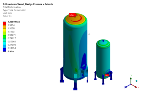
The different loads on Vessel are taken as per input data sheet and design data provided by client. Analysis is performed using licensed and widely accepted software and results post processing is performed as per guidelines of ASME section VIII DIV. 2 Part 5 Ed. 2023. FEA results are validated with analytical approach such as Hoop stress validation and global equilibrium check.
The numbers of fatigue cycles are calculated based on amplitude stresses during cyclic loading condition. To evaluate fatigue damage factor, required comparison between fatigue life cycles from FEA and number of design cycles. Required number of Design life Cycle is client provided.