Compression in a screw compressor is achieved by intermeshing of male and female rotors. The male rotor has four lobes and the female rotor normally has six flutes. Power is applied to the male rotor and as lobe of the male rotor starts to move out of mesh with the female rotor, a void is created where the gas rushes to fill in through the inlet port.
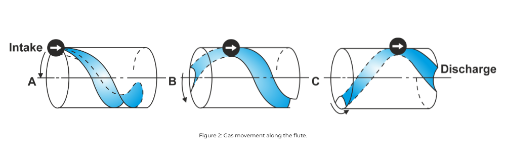
As the rotor turns, the intermesh space increases, and the gas continuously flow into the entire inter lobe space until it is filled. With the continued rotation, a male lobe helps to reduce inter lobe space, which compresses the gas and moves the same to the direction of discharge port.
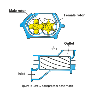
The volume of the gas is progressively reduced, which increases the pressure. Further rotation uncovers the discharge port and compressed gas starts to flow out of the compressor. Continued rotation moves the balance of the trapped gas out while a new fill is drawn into the section of the unmeshing of a new pair of lobe and flute and the compression cycle begins.
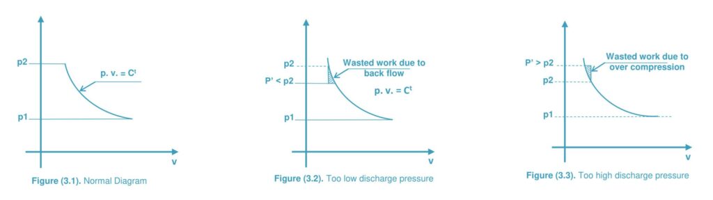
As the length of compression is fixed with the designed volume of the trapped gas at the start of compression cycle and the volume of the gas just prior to the opening, the pressure ratio remains constant.
To overcome the loss in efficiency, the compressor porting is physically arranged to match the application pressure ratio.
To maintain the best efficiency, it is important that the matching be as close as possible.
Let us analyse two cases::
- Case 1 – Low pressure ratio compressor (Figure 4.1)
- Case 2 – High pressure ratio compressor (Figure 4.2)
Figure 4.3 is depiction of a low pressure ratio unit operating in a higher-than-design application. As the gas arriving at the discharge port has not been sufficiently compressed, the result at negative ratio across the discharge port causes a back flow and resulting loss of energy.
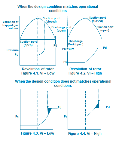
Figure 4.4 shows a compressor with too high pressure ratio for the process. Here the gas is compressed higher than needed to match the pressure of the gas on the outlet side of the discharge port, resulting in energy loss.
From figure 4.1 & 4.2, it is clear that the volume of trapped gas at the start of compression cycle and the volume of the gas just prior to the opening of discharge port determines the design pressure ratio of the screw element.
In a simplified way, this can attributed to the ratio of these two volumes, which is known as volume ratio.
𝑉𝑖 (𝑣𝑜𝑙𝑢𝑚𝑒 𝑟𝑎𝑡𝑖𝑜)= (𝑉𝑜𝑙𝑢𝑚𝑒 𝑜𝑓 𝑡𝑟𝑎𝑝𝑝𝑒𝑑 𝑔𝑎𝑠 𝑎𝑡 𝑠𝑡𝑎𝑟𝑡 𝑜𝑓 𝑐𝑜𝑚𝑝𝑟𝑒𝑠𝑠𝑖𝑜𝑛)/(𝑉𝑜𝑙𝑢𝑚𝑒 𝑜𝑓 𝑔𝑎𝑠 𝑗𝑢𝑠𝑡 𝑝𝑟𝑖𝑜𝑟 𝑡𝑜 𝑑𝑖𝑠𝑐ℎ𝑎𝑟𝑔𝑒 𝑝𝑜𝑟𝑡 𝑜𝑝𝑒𝑛𝑖𝑛𝑔)
To match the desired pressure ratio, process screw compressors are designed with various volume ratios.
rp= Vi^k
Where,
- r_p = Pressure ratio
- Vi = Volume ratio
- k = Isentropic exponent
Screw element are designed with a series of Vi (volume ratios).Fixed volume ratio are designed between 1.8 to 5.5 in steps and the most efficient pressure ratio with be based on the k (Cp / Cv) value of the gas. In case of various pressure ratio or change in “k” due to change in gas composition, a variable Vi can be installed. The effect in adiabatic efficiency – pressure ratio – Vi is shown on the curve on the Figure 5.1.
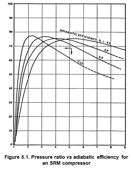
Hence it is important to select the right volume ratio to avoid the energy loss.
References: Royce N. Brown, Compressors: Selection and Sizing, 3rd edition